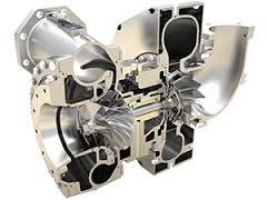
Most modern Diesel engines are now fitted with a turbocharger for improved efficiency and higher power output. A turbocharger consists essentially of a turbine driven by the exhaust gases leaving the engine, directly connected to a rotary compressor. The compressor forces more air into each cylinder than is possible when relying upon atmospheric pressure to do the job. This means that more fuel can be injected and burned in each cylinder – hence the engine develops more power. Turbochargers respond to engine load: the harder the engine is working, the higher the exhaust gas velocity and the greater the increase in the inlet air pressure. This helps to give turbo-diesel engines their characteristically high torque at low engine speeds.
Turbocharger components operate at very high speeds (typically in excess of 100,000 rpm when under load) and at high temperatures (up to red heat). These factors, combined with the precision bearings that are necessary for operation at these high speeds, place stringent requirements on the lubrication system. Any dirt particles entering the turbocharger bearings can lead to sudden and dramatic bearing failure.
Perkins Engines recently launched a new series of Diesel engines using a number of different turbo oil feed and drain pipe assemblies, each typically consisting of a complex three-dimensional multi-bend tube incorporating at least one section of flexible hose. The end fittings are flange, olive or banjo connections. Stringent specifications were laid down regarding cleanliness of the pipes supplied to Perkins, and they had to be guaranteed free from leaks.
Cambridge Dynamics have worked closely with many manufacturers over the years to provide solutions to production challenges such as this. In the present case it was decided to build an automatic flushing rig that would rigorously flush any debris from the manufactured pipe assemblies and then go on to perform a leak test. Rapid changeover from one type of pipe to another was a prime requirement so Cambridge Dynamics designed the rig to accept quick-change pre-set tooling for each type of pipe. The operational characteristics of the rig are fully programmable, and multiple programmes can be stored in the control system.
The rig consists of a pipe cabinet fitted with six sets of tooling arranged vertically, allowing six pipes to be processed concurrently. The pipes are loaded manually, and the tooling incorporates simple but effective clamping of the pipe end fittings to ensure rapid, leak-free connections between the tooling and the pipe. A clear vertical sliding guard encloses the pipes while flushing and leak testing takes place. A large fluid power pack includes a high capacity pump and pneumatically-operated diverter valves to allow fluid to flow though the pipes in both directions.
A typical flushing cycle consists of a programmable number of flushes upwards and downwards through the pipes, each for a set time. During flushing the control system checks for the correct pressure drop across the pipe as a simple test that the pipe is not blocked. Once the flushing sequence is complete the pump is used to pressurise the pipes at up to 20 bar. Poppet valves at both ends of each pipe then trap this pressure in the pipes, and the pump stops running. Pressure transducers connected to each pipe are used to check that there are no leaks, by ensuring that the pressure does not fall below a programmable threshold at the end of a programmable leak test time. When the leak test is complete the flushing fluid is purged from the pipes by a blast of compressed air. Once the purging is complete the guard slides down and the pipes are immediately accessible for removal.
The control system employs a Telemecanique-Modicon Programmable Logic Controller from the successful Premium family, and an ASi network carries all the rig digital and analogue signals on just two 2-core cables. The operator interacts with the control system by means of a Magelis colour touch-screen display unit. Helpful animated pictograms indicate the various stages in the flushing and leak testing sequence, and the results for each pipe assembly are presented here.
The same screen allows the display of clear messages when errors are detected by the extensive in-built diagnostic system. For example, if one of the diverter valves fails to move when expected the status of all the relevant solenoid valves and sensors in that area is displayed, together with an indication of the most likely cause of the problem.